PCB Assembly Requirements for RF and Telecom Communication Boards
RF and telecom communicat


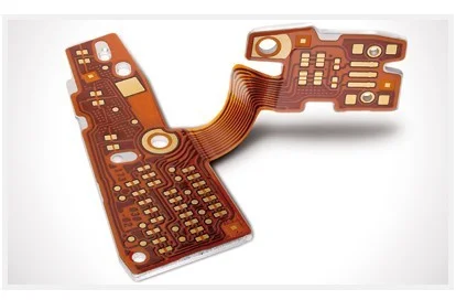
Flexible circuits offer significant advantages for compact electronic designs, wearable devices, and dynamic moving applications. However, the transition from a successful prototype to mass production often reveals hidden engineering challenges. While rigid boards follow predictable assembly patterns, flex PCB assembly requires specialized handling, tooling, and process controls.
If buyers do not verify specific manufacturing capabilities and design rules before releasing files, production yields can drop significantly. This article explores the core engineering risks associated with flexible circuit board assembly and outlines what buyers must confirm before starting mass production.
Lack of Proper Carrier Support Unlike rigid boards, flexible circuits cannot be fed directly into standard SMT pick-and-place lines or reflow ovens without support. If a flex circuit is not properly palletized or mounted on a rigid carrier board, the high temperatures of the reflow process will cause the polyimide material to expand, warp, or wrinkle. This movement destroys the precise alignment required for fine-pitch components and BGAs, leading to open circuits or solder bridges.
Thermal Expansion Mismatch The coefficient of thermal expansion (CTE) in flexible materials differs from that of rigid FR4. During the soldering process, copper traces and polyimide substrates expand at different rates. If the assembly process does not account for this thermal behavior, it can cause micro-cracks in the copper traces or delamination of the coverlay. Buyers must ensure the manufacturer uses appropriate thermal profiling and carrier materials designed specifically for flex circuits.

Coverlay Bubbling and Delamination Flexible circuits typically use coverlay instead of traditional solder mask to protect the copper traces. The adhesive layer bonding the polyimide coverlay to the copper base is highly sensitive to thermal shock. During multiple reflow cycles, trapped moisture or inadequate adhesion can cause the coverlay to bubble or peel away from the pad edges. This not only compromises the electrical insulation but also makes subsequent assembly steps impossible.
Moisture Sensitivity in Polyimide Materials Polyimide is highly hygroscopic, meaning it absorbs moisture from the environment easily. If flex circuits are not baked or stored in dry cabinets before assembly, the absorbed moisture will rapidly vaporize during reflow soldering. This vapor pressure can blow out the coverlay or create voids in the solder joints. Buyers should verify that the assembly facility has strict moisture sensitivity device (MSD) handling protocols for flexible materials.
Stiffener Thickness Variations Many flex PCB designs require rigid stiffeners (made of FR4, PI, or steel) to provide mechanical support for connectors or mounting holes. The adhesive bonding process for these stiffeners introduces a new layer of thickness tolerance. If the stiffener is not perfectly flat or if the adhesive layer is uneven, it will directly affect the Z-axis height of the surface mount connectors.
Connector Coplanarity Issues For zero-insertion-force (ZIF) or flat flexible cable (FFC) connectors, coplanarity is critical. A height variation of even a few mils across the connector pins can result in poor contact or damaged mating cables in the final product. Buyers must require the manufacturer to perform 3D optical inspection or laser scanning to verify connector coplanarity after the stiffeners are applied and the components are soldered.
Mechanical Damage During Separation Rigid PCBs are typically depaneled using V-score routing, mechanical scoring, or CNC milling. These methods are destructive to flexible circuits. Using a standard router bit on a flex board can cause the polyimide layers to tear, create copper burrs, or damage the edge traces.
Laser Depaneling Requirements To separate flex circuits safely, manufacturers must use laser depaneling or specialized precision punching tools. The laser process vaporizes the material without applying mechanical stress, ensuring clean edges and intact copper traces. Buyers need to confirm that the assembly supplier has laser depaneling capabilities and that the Gerber files include proper tooling rails and breakaway tabs designed for laser cutting.
Probe Pressure and Board Bending In-circuit testing (ICT) and functional testing rely on spring-loaded pogo pins pressing against test pads. On a rigid board, this downward force is easily resisted. On a flex circuit, the probe pressure will push the board downward, causing it to bend. This bending can lead to intermittent test contacts, false failures, or even physical damage to the component pads and traces.
Vacuum Fixture and Support Solutions To solve this, the test fixtures for flexible circuit board assembly must incorporate vacuum chucks or custom support blocks that hold the flex area completely flat during probing. Designing these fixtures requires close collaboration between the test engineering team and the PCB design team. Buyers should ask for the test fixture design review report before approving the production test plan.
Understanding the difference in assembly requirements helps buyers evaluate supplier capabilities accurately.
| Assembly Stage | Standard Rigid PCB Assembly | Flex PCB Assembly | Buyer Verification Point |
|---|---|---|---|
| SMT Support | Direct conveyor transport | Requires rigid carrier/pallet | Confirm carrier design and palletizing process |
| Reflow Profile | Standard thermal profile | Custom profile for polyimide CTE | Request thermal profiling data for flex materials |
| Edge Separation | CNC routing or V-score | Laser depaneling or precision punch | Verify laser equipment and tooling rail design |
| Test Fixture | Standard spring probes | Vacuum hold-down or custom support | Review fixture design for pad protection |
| Inspection | Standard AOI | AOI + 3D coplanarity check for connectors | Ensure 3D inspection for ZIF/FFC connectors |
Before sending files for quotation, buyers must ensure their design supports the physical realities of flex assembly. A thorough PCB design review should address the following:
For projects combining rigid and flexible sections, buyers should also review the capabilities related to Rigid-Flex PCBs to understand the lamination and plating requirements for the transition zones.

RF and telecom communicat
Choosing a PCBA manufactu