
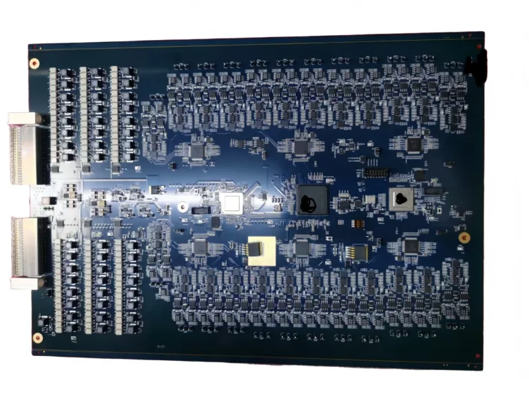
PCB Assembly Requirements for RF and Telecom Communication Boards
RF and telecom communicat


A flex PCB usually costs more than a standard rigid PCB when buyers compare only the bare boards. That comparison can be misleading. A flexible circuit may replace cables, connectors, and manual wiring inside the final product. A rigid PCB may remain the lower-cost and more reliable choice when the board stays flat and supports heavier components. The correct decision depends on movement, installation space, assembly work, connector count, and the expected product environment. Cost and reliability must be reviewed at the full system level, not only at the PCB quotation level.
A rigid PCB provides a stable platform for components and electrical connections. Many rigid boards use glass-reinforced epoxy laminates such as FR-4. The structure supports standard drilling, lamination, component placement, soldering, inspection, and mechanical mounting.
A flex PCB uses thin, bendable dielectric materials. Polyimide-based laminates are common in flexible circuits. The circuit can fold, curve, or move inside a compact product. Flexible material systems may include polyimide film, copper foil, adhesive, and protective coverlay.
The main difference is not simply that one board bends. Each structure solves a different packaging problem.
A rigid PCB works well when the board remains flat. It can support connectors, transformers, shielding parts, heat sinks, and other components that need a stable mounting area.
A flex PCB works well when the circuit must cross an enclosure, fold around another part, connect moving sections, or replace a wiring harness.
Neither structure is automatically more reliable. Reliability depends on how the board is used.
| Decision factor | Rigid PCB | Flex PCB | Cost or reliability effect |
|---|---|---|---|
| Mechanical form | Flat and mechanically stable | Can bend, fold, or conform | Flex supports compact three-dimensional layouts |
| Common dielectric | FR-4 or another rigid laminate | Polyimide-based flexible laminate | Flex materials and processing often cost more |
| Component support | Good without local reinforcement | Stiffeners may be needed | Stiffeners add material and process steps |
| Repeated movement | Not intended for bending | Possible with a dynamic flex design | Bend requirements must be defined early |
| Assembly handling | Standard panel and fixture methods | May need carriers or support tooling | Flex handling can increase assembly work |
| Internal wiring | May need cables and connectors | Can replace some cables or harnesses | Flex may lower total installed cost |
| Repair and replacement | Individual boards may be easier to replace | Integrated circuits may be harder to replace | Service strategy can affect lifetime cost |
| Best cost comparison | Bare-board and assembly cost | Complete interconnect system cost | Unit PCB price alone is not enough |
The bare-board price of a flex PCB is usually higher than the price of a simple rigid PCB. This difference comes from materials, manufacturing steps, panel use, handling, and inspection.
Flexible materials cost more.
Flexible circuits use specialized laminates, coverlays, adhesives, and copper options. The material system must survive bending without creating cracks or delamination. Flexible copper-clad laminates are available in several copper types, dielectric thicknesses, and adhesive constructions because the mechanical requirement varies by project.
The fabrication process needs tighter mechanical control.
Thin flex materials can move, stretch, or distort during fabrication. Registration, drilling, imaging, lamination, and outline control therefore need careful process planning.
Coverlay replaces standard solder mask in many areas.
A coverlay protects the copper while allowing the circuit to bend. Openings must match pads and contact areas. Small or crowded openings can increase tooling and alignment difficulty.
Stiffeners may be required.
A flexible circuit cannot support every component or connector by itself. FR-4 or polyimide stiffeners may be added below connector fingers, component areas, or mounting holes. Minco describes stiffeners as reinforcement for component mounting and also distinguishes them from true rigid-flex constructions.
Panel utilization can change the cost.
A long, narrow, curved, or irregular flex outline may use panel space poorly. More material can become scrap. Small changes to the circuit outline or array direction can affect the number of usable circuits per production panel.
Assembly may require additional support.
A thin flex circuit may need a carrier during solder paste printing, pick-and-place, reflow, inspection, or depaneling. The required fixture depends on board thickness, component weight, stiffener location, and assembly side.
For these reasons, buyers should not expect a flex PCB quote to match a same-size rigid PCB quote.
A higher PCB price does not always mean a higher product cost.
The correct comparison is:
PCB fabrication + connectors + cables + assembly labor + inspection + rework + mechanical hardware + field failure risk
A flex PCB can combine several electrical connections into one manufactured circuit. It may replace loose wires, ribbon cables, board-to-board connectors, and manual soldered connections.
This can reduce:
Flexible circuit manufacturers note that a single flex circuit can replace several rigid boards, connectors, and wiring elements in some product architectures. The benefit comes from simplifying the interconnect system, not from making the flex circuit itself cheaper.
This cost advantage is project-dependent.
A simple product with one flat board will probably not gain enough value from a flex PCB. A compact product with several connected modules may show a different result.
The engineering team should compare the complete bill of materials and assembly sequence for both options.
The word “flexible” does not mean that every flex PCB can bend in the same way.
The manufacturer must know how the circuit will move.
Static installation
The circuit stays in one position during normal operation. It may be shaped during assembly, but it does not move afterward.
A rigid PCB is often suitable when the product has enough flat mounting space.
A flex PCB may still be useful when the board must fit around a corner or cross between different enclosure levels.
Flex-to-install use
The circuit bends during product assembly or maintenance. It then remains in a fixed position.
IPC identifies flexible-board uses that must withstand flexing during installation. The fabrication drawing should therefore identify the bend zone and installation condition.
Dynamic flex use
The circuit moves repeatedly during product operation. Hinges, print heads, moving sensors, robotic joints, and other mechanisms may create this condition.
A dynamic flex circuit needs a defined movement path. The designer should confirm the bend radius, flex length, layer construction, copper type, trace geometry, stiffener transition, and target cycle requirement.
Flex life is not a fixed property of the material. It changes with the complete construction and mechanical design. IPC treats flexible and rigid-flex design as a separate discipline because fabrication, assembly, documentation, and use conditions all affect the result.
Important reliability risks in a flex design
Copper can experience repeated strain inside the bend area. Sharp folds, thick constructions, abrupt stiffener edges, plated holes, component pads, and poorly positioned traces can concentrate stress.
The design should avoid placing rigid features inside the active bend area. The bend should follow a smooth and controlled path. The manufacturer should review the final stack-up before the design is released.
A flex PCB designed only for installation should not be treated as a dynamic flex circuit.
A rigid PCB provides stable mechanical support. It does not depend on a controlled bending zone.
This makes it suitable for products with:
A rigid structure also simplifies component planarity during stencil printing and placement. Standard carriers, panel rails, breakaway tabs, and inspection methods are widely used.
However, a rigid PCB may need separate cables or connectors when the product contains several board sections.
The rigid board can remain reliable while the interconnect system becomes the weak point. Connector fretting, incomplete mating, cable damage, soldered-wire strain, and assembly errors may then affect the complete product.
The reliability review must therefore include everything between the boards.
Connectors are not automatically unreliable. Many connector systems perform well when the correct type, mounting method, retention, plating, and mechanical support are used.
They still add parts and interfaces.
A rigid-board architecture may require:
Every connection must be purchased, mounted, mated, and checked.
A flex circuit may remove some of these interfaces. A rigid-flex PCB can integrate rigid component areas and flexible connections into one structure. Minco notes that eliminating flex-to-rigid transition connections can improve system reliability, although rigid-flex fabrication costs more than a standard flex circuit with stiffeners.
Rigid-flex is not the same as a standard flex PCB. It is a third option.
Topline Circuit has separate pages for Flexible PCBs and Rigid-Flex PCBs because the constructions, manufacturing steps, and project uses differ.
Choose a rigid PCB when the project has a stable mechanical structure and does not need bending.
A rigid board is usually the stronger option when:
A standard FR4 PCB can meet many general electronic requirements. Material, Tg, copper weight, stack-up, and surface finish still need confirmation from the project files.
Do not choose flex only because the product is small. A compact rigid PCB may still be simpler and less expensive.
Choose a flex PCB when the electrical connection must follow the product’s mechanical shape.
A flex circuit becomes useful when:
The mechanical drawing should drive this decision.
The PCB designer needs the actual enclosure geometry, bend position, installation path, and movement condition. A flat Gerber view does not fully describe how the circuit will work inside the product.
Early cooperation between the mechanical engineer, PCB designer, and manufacturer reduces late layout changes.
The bare-board comparison may look like this:
The complete product comparison may look different:
Compared with:
The second structure may cost less at the system level. It may also cost more. The result depends on connector type, circuit complexity, assembly volume, panel use, inspection, testing, and expected field conditions.
No fixed percentage can answer this comparison.
The supplier should quote both designs from complete files when the cost difference is important.
For a broader review of BOM and assembly expenses, see PCB Assembly Cost Factors Buyers Should Understand.
A Practical Selection Matrix
| Project condition | Recommended starting direction | Reason |
|---|---|---|
| One flat PCB with no movement | Rigid PCB | Simple structure and standard assembly |
| Board must fold once during installation | Flex PCB | Supports three-dimensional installation |
| Circuit moves repeatedly | Dynamic flex PCB | Designed around controlled movement |
| Heavy components sit near the connection area | Rigid PCB or stiffened flex | Mechanical support is required |
| Several rigid boards use cables and connectors | Compare flex or rigid-flex | Total interconnect cost may change |
| Lowest bare-board price is the main goal | Rigid PCB | Standard materials and processes |
| Connector height blocks enclosure closure | Flex PCB | Can reduce connector volume |
| Product needs separate replaceable modules | Rigid PCB may be preferred | Individual boards can remain serviceable |
| Tight enclosure with several mounting planes | Flex or rigid-flex | Supports compact spatial routing |
| Mechanical requirements are still uncertain | Complete mechanical review first | The board type should follow the enclosure |
Mistake: Choosing flex only to save space
Flex can save space, but it also needs a clear bend path. A crowded enclosure may pinch the circuit or force a sharp fold.
The mechanical design must reserve space for a controlled curve.
Mistake: Treating every bend as dynamic
A circuit folded once during assembly has different requirements from a circuit moving every second.
The drawing should state whether the application is static, flex-to-install, or dynamic.
Mistake: Ignoring stiffener transitions
A stiffener supports connectors and components. Its edge can also create a stress concentration.
The transition location should stay outside the active bend area.
Mistake: Comparing only PCB quotations
A rigid board quote may exclude connectors, cables, wiring labor, and mechanical hardware.
Compare the complete installed architecture.
Mistake: Sending only Gerber files
Gerber files show copper and board geometry. They do not explain product movement, bend radius, connector mating force, or enclosure clearance.
Flex projects need mechanical information.
Prepare the following data before requesting a flex PCB vs rigid PCB quotation:
Topline Circuit’s PCB manufacturing review can compare material, stack-up, outline, bend areas, and fabrication requirements. Flex assembly projects should also identify the carrier, component side, stiffeners, connector support, and inspection plan.
For assembly quotations, the article What Files Are Required for an Accurate PCB Assembly Quotation? explains how Gerber, BOM, placement, and assembly data affect the review.
Our team can help you evaluate the board structure, materials, component assembly, and testing requirements based on your product’s operating environment and performance needs.

RF and telecom communicat
Choosing a PCBA manufactu